MCA Benefits
ISA Static Grounding
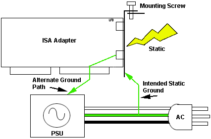
The PC and AT board bracket is designed to be grounded
to the chassis ground via the mounting screw. If the mounting screw is
loose or missing, then there is no straight path to ground. If the mounting
bracket is not electrically isolated, then there are only the 3 pins on
the PC Bus, which were intended only to provide a logic reference, to ground
the static.
If the mounting screw is not tight, static may go to ground
through the card circuitry, possibly causing data alteration. Also, the
mounting screw does not guarentee that the card is actually centered in
the slot.
The design of the PC/AT bus is quite simple, with only
three ground lines in either design.On the motherboard, the shielding is
adequate, but once the signals rise up into the adapters, the shielding
is much less and the signals radiate more.Testing puts the limit to the
PC/AT bus around 30-34 MHz due to generated interference.
MCA Static Grounding
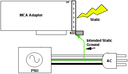
The MCA grounding and mounting scheme eliminates the problems
of the ISA bracket. The MCA slot bracket has several spring fingers to
maintain positive contact with the sides of the slot. The metal bracket
blocks radiation that would otherwise leak from the slot. It is electrically
isolated from the card circuitry, thus reducing the possibility of data
alteration.
Instead of depending on a mounting screw at the top, the
mounting bracket actually fits inside of a frame that is at the rear of
the system, and this provides positive centering of the adapter.In addition,
the V-shaped slot at the bottom of the MCA slot bracket fits around a knurled
thumbscrew, ensuring a tight fit.
The MCA bus is laid out with every fourth pin on each
side of the connector either power or ground. Since the power connection
offers about the same shielding ability as a ground, every signal is within
1/10th of an inch or less of a shielding lead. This allows an upper operating
frequency nearly three times that of the PC bus.
9595 Main Page
|