7007-N40
194-062 IBM RISC System/6000 N40 Notebook Workstation
194-235
IBM RS/6000 Model N40 Features And Enhancements
194-324
IBM RISC System/6000 Sorage I/O (810MB drive)
294-114 IBM AIX For N40
Memory Specs
LED PCB, Top
LED PCB, Bottom
Keyboard
Hard Drive
7007-N40 Ports
PCMCIA Slot IDs
PCMCIA Flap
Install / Remove Memory
Hacking the SPARCbook
Memory Specs
It supports main memory sizes from 16 to 64MB. SIMMs are 5v,
70 ns, Fast Page Mode operation, and are no more than 1-inch high.
NOTE: Install SIMMs in pairs.
SIMM sockets are gold plated. Memory in mine are NEC
MC-424000A36BD-70, PD is 67 and 69 shorted.
ICs on both ends are 2x NEC 4217400-70, 2x NEC 424100-70 in the
middle, and a further 2x NEC 4217400-70 for a total of 6 chips per side
of the SIMM.
Following chip IDs from Chiplist
4217400 4M*4 DRAM* fast page 2K ref (NEC)?
424100 4M*1 DRAM fast page
LED PCB, Top

LD1 Power LED
LD2 Battery Warning LED
SK1
SK2
SK3,4 Keyboard tapes
SK5 Trackpoint tape |
SP1 Speaker
SW1 Power switch
U2 RTC 6413
U5 LCD
XL2 H15.6250B4 xtal
1 |
LED PCB, Bottom

| U6 FC48 1.26 |
U8 Dallas DS1267S-010 |
Microcontroller module
Microcontroller Subsystem (H8-337)
A Hitachi H8/337 microcontroller is provided to offload
system housekeeping tasks from the main CPU. The microcontroller
features used in this design are:
32K internal ROM, 1K internal SRAM
Choice of mask ROM, or OTP EPROM
Sixteen bit timer
PWM outputs (Beeper)
Three 8-bit A-D converters (Internal Temp and Keyboard
Pointer)
Two 8-bit D-A converters (LCD contrast / battery
charging level)
Two serial ports (External Sun Keyboard and Mouse)
Sleep mode (for power saving)
The microcontroller subsystem handles the following functions:
Internal keyboard and pointing device control
External Sun keyboard and mouse control
Serial communication channels to SLAVIO keyboard
and mouse ports
PSU and battery energy management
System non-volatile storage (RTC and serial EEPROM)
Environmental Parameter control (display brightness
/ audio volume)
LCD status display (2 x 16 character) control (environmental
and diagnostic functions)
System reset control
Power management control
Keyboard
Lexmark P/N 1403213, Model M6. The keyboard with embedded pointing
device is sourced from Lexmark Inc., and is derived from the unit used
in IBM's industry acclaimed ThinkPad 750 product.
Hard Drive
Lots of luck with this. Check HERE
for info.
Disks for
7007 (Used in Sun Voyager, Powerlite 170)
Toshiba
MK2326FB 340 MB 4200 RPM 7.5 ms 12 ms 19mm
MK2428FB 524 MB 4200 RPM 7.5 ms 12 ms 19mm
MK2526FB 524 MB 4200 RPM 7.14 ms 13 ms 19mm
MK2628FB 811 MB 4200 RPM 7.14 ms 13 ms 19mm
IBM
DPRS-20810 810 MB 4900 RPM 6.1 ms 12 ms 17.5mm
DPRS-21215 1215 MB 4900 RPM 6.1 ms 12 ms 17.5mm
DMCA-21080 1080 MB 4000 RPM 7.5 ms 13 ms 12.5mm + adaptor
The 810MB Removable Disk Drive for the N40 provides significantly
higher disk capacity than was previously available in a 2.5-inch disk.
This permits the Model N40 notebook system to accommodate larger data files
and more applications than with the 540MB disk.
810MB SCSI-2 Removable Disk Drive FC #2519
810MB SCSI-2 Removable Disk Drive Select FC #2520
Travelstar
XP SCSI Jumper settings Model: DPRS-20810 / -21215
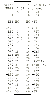
SCSI address settings (J2 pins)
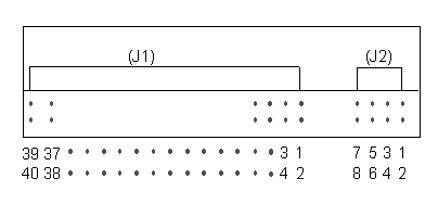
5(-ID1) 6(-ID2) 7(-ID4) ID
open open open
0
GND open open
1
open GND open
2
GND GND open
3
open open GND
4
GND open GND
5
open GND
GND 6
GND GND
GND 7
Note: The drive does not have termination or pull
up resistors for the SCSI interface.
7007-N40 Ports
Thanks to Stefan Tibus for helping me wade through the ports 'o call...

DC Power (2.1mm x 5.5mm)
Radio Shack Type N Plug
12 volt DC 4.6 Amp. Tip positive.
SCSI Port (HDI-30)
Allows you to connect external hard disks, tape drives, and
CD-ROM drives.
1 NC
11 ID(4) 21 REQ
2 ID(0)
12 GND
22 GND
3 GND
13 GND
23 BSY
4 ID(1)
14 ID(5) 24 GND
5 TERMPWR 15 GND
25 ATN
6 ID(2)
16 ID(6) 26 CD
7 ID(3)
17 GND
27 RST
8 GND
18 ID(7) 28 MSG
9 ACK
19 ID(PARITY) 29 SEL
10 GND
20 GND
30 ID
Parallel Port (HDI-30)
Allows for the connection of devices such as printers
and scanners.
1 GND
11 GND
21 DATA(4)
2 STROBE
12 BUSY 22
DATA(6)
3 GND
13 SLCT 23
GND
4 DATA(1) 14 GND
24 ACK
5 +5V(*)
15 ERROR 25 GND
6 GND
16 SELECT-IN 26 PE
7 DATA(3) 17 GND
27 GND
8 DATA(5) 18 DATA(0)
28 AUTOFEED
9 GND
19 DATA(2) 29 INIT
10 DATA(7) 20 GND
30 GND
(*) protected by internal fuse with automatic reset
Video Port (HDD15)
Allows you to connect external displays.
1 red
6 GND
11 ID(0)
2 green
7 GND
12 ID(1)
3 blue
8 GND
13 HSYNC
4 ID(2)
9 NC
14 VSYNC
5 GND
10 GND
15 ID(3)
Mouse Port (6 pin mini-DIN)
The mouse port allows you to connect a PS/2-compatible
mouse. The external mouse operates simultaneously with the Pointing Stick.
1 DATA
4 +5V
2 SLAVETX
5 CLOCK
3 GND
6 SLAVERX
LocalTalk (8 pin mini-DIN)

1 HANDSHAKE OUT 5 RECEIVE-
2 HANDSHAKE IN 6 TRANSMIT+
3 TRANSMIT- 7 GPINPUT
4 GND(chassis) 8 RECEIVE+
Keyboard/Mouse Port (6 pin mini-DIN)
Allows you to connect a PS/2-compatible keyboard and mouse.
The external keyboard operates simultaneously with the built-in keyboard.
The external mouse operates simultaneously with the Pointing Stick.
1 DATA
4 +5V
2 SPEAKER+ 5 CLOCK
3 GND
6 SPEAKER-
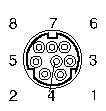
Serial Port (8 pin mini-DIN)
The serial (or TTY) ports allow the connection of devices such as serial
printers, terminals, and external modems.
|
Pin
|
Signal
|
Pin
|
Signal
|
|
1
|
DTR
|
5
|
RCV DATA
|
|
2
|
CTS
|
6
|
RTS
|
|
3
|
XMIT Data
|
7
|
DCD
|
|
4
|
Chassis Gnd
|
8
|
TX CLOCK |
Headphones (1/8" stereo mini jack)
Stereo headphone socket provided for personal listening.
A 1/8-inch stereo speaker jack is provided for situations where additional
amplification is necessary.
Audio In/Out Port (8 pin mini-DIN)
The audio interface provides stereo line-in and line-out
connections. It allows stereo sound input from an external sound source,
such as a microphone or CD player, to be recorded and stored by your Tadpole
and then played out to external audio equipment.
A full 16-bit audio function has been designed into the
system. Two audio ports are provided to complement the built-in microphone
and speaker. The other audio port has a fan-out connector with four RCA-type
jacks. Two of the jacks are for stereo inputs and two are for stereo outputs.

1 LINE-OUT left 5 GND(audio)
2 GND(audio) 6 LINE-IN right
3 LINE-IN left 7 GND(audio)
4 GND(audio) 8 LINE-OUT right
Ethernet Interface (DB15 AUI)
The Ethernet interface allows connection to a wide variety
of LANs via an external transceiver.
1 GND
6 GND
11 GND
2 COLLISION+ 7 NC
12 RX-
3 TX+
8 GND
13 +12V(*)
4 GND
9 COLLISION- 14 GND
5 RX+
10 TX-
15 NC
(*) protected by internal fuse with automatic reset
ISDN Interface (RJ-45)
The ISDN interface allows connection to ISDN services
provided by telephone companies.
1 NC
5 TE IN-
2 NC
6 TE OUT-
3 TE OUT+
7 NC
4 TE IN+
8 NC
Internal Modem Interface (RJ-11)
The integrated modem is a V.32 bis data (300-14.4k)/V.17 FAX
(300-14.4k) modem. It is an auto-dialing/answer data/FAX modem.
It includes error-correction, data compression, data security, and power
management functions.
1 NC
4 TIP
2 NC
5 NC
3 RING
6 NC
PCMCIA Port Identity
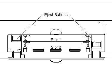
Your Tadpole has two PCMCIA slots. Slot 1 is nearest the keyboard top,
and Slot 0 (zero) is furthest from the keyboard top.
PCMCIA Port
Flap
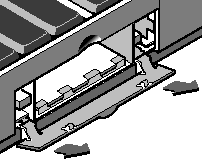
The PCMCIA port’s flap can be removed for convenience.
This is useful if you wish to install an interface card, such as a modem,
which uses a connecting cable. The door is retained by clips at its hinges.
Remove PCMCIA port flap:
1. Open the door to an angle of about 60 degrees.
2. Pull firmly to release the hinge pins from the hinge clips.
Replace PCMCIA port flap:
1. Locate the hinge pins so that they both touch the hinge clips, with
the door at an angle of about 60 degrees.
2. Apply a steady but firm pressure until the hinge pins clip into
place under the springs.
Install
/ Remove Memory
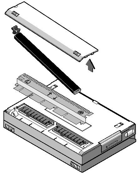
Preparing to Remove the SIMMs
1. Ensure that your Tadpole is powered off by carrying out a system
shutdown, as described in “Powering off using a system shutdown” and is
not connected to an external power supply unit.
2. Close lid and place your computer upside down on a level surface.
3. Remove battery cover and battery.
4. Placing the forefinger of the left hand on the L symbol and the
forefinger of the right hand on the R symbol on the SIMM cover, gently
pull the SIMM cover toward yourself with your forefingers until the rearmost
row of clips disengage from the base casting. Then, with your thumbs, press
the cover towards the rear of the unit until the clips (normally) located
beneath the battery disengage.
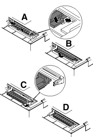
Removing the SIMMs
1 Gently press the latches of the first SIMM socket outward until the
SIMM pops up (see views A and B). This frees the SIMM for removal.
3. Remove the SIMM.
4. Repeat for the second SIMM.
Installing SIMMs
1. Hold the SIMM with contact edge points away from you and the cut-out
edge on the right. Place the SIMM’s contact edge against the SIMM connector
(see views C and D).
2. With contacts in position, gently press the SIMM downwards until
latches click into place.
3. Repeat steps 3 and 4 with the second SIMM.
4. Replace the SIMM cover.
5. Replace the battery and battery cover.
Checking the SIMMs
(pulled from SPARCbook, unk)
1. Power your N40 on.
2. When the OpenBoot greeting is displayed, press Pause-A.
3. Check that new memory capacity is correctly reported on display.
4. Power off by pressing Pause-O.
INTERNAL BATTERY PACK (10xAA NiMh
1,100mAh) (#7090)
This is a rechargeable battery pack, made up of 10 AA-sized
Nickel Metal Hydride (NiMH) cells, that fits inside the main unit covers
(in a compartment under the keyboard). It is also chargeable if fitted
into the Internal Battery Pack Storage charger. Energy capacity is
approximately 1,100mAh. The battery life under normal operation is
approximately 45 minutes. incorporating temperature sensor and charge mechanism
Sunder wrote:
From what I understand, there is a thermoresistor in there,
so when you crack it open, be careful not to rip it out. Just replace
all ten cells with new NiMH AA's and you should be good. You can
probably even go to the higher capacity NiMH's that are 1800ma from say
cyberguys.com
External Battery Pack and Cable
(10xD NiCd 5700mAh) (#7091)
A rechargeable battery pack, that is attached externally
to the main unit. It can be connected either by a snap-on connection of
the battery pack unit to the rear of the system, or it can be connected
via cable, with the battery pack free-standing (not attached). It is made
up of 10 D-sized Nickel Cadmium (NiCd) cells, and the charger for the battery
pack with a capacity of approximately 5700mAh. The battery life with typical
use scenarios is greater than 4 hours.
Power Supply: External 60W, system input voltage
12V, 4.6A
Interesting box, made by Tadpole of UK.
Unixguys sighs:
Yup .... but after IBM pulled the plug on Tadpole and decided to build
their own risc laptop (820-60 later discontinued) Tadpole sent all the
tooling back to IBM and threw everything else out. The only thing on their
site are a few patches. There was a lot of bad blood over this exersize.
During the CeBIT I saw the N40 RISC-notebook from IBM with the Power-Chip
inside. The machine had WABI as a beta installed and you could see the
Windows Programmanager sitting on the AIX Motif desktop (showing a GPF
;)) .
The display was a normal 640*480 TFT(?) LCD screen. There was some sort
of harware-zoom, you could magnify parts of the virtual 1280*1024 desktop
and move it around on the display.
The machine could be equipped with 64MB of RAM and has a 300 MB harddisk.
After the AIX and the paging space is gone you should have approx. 100MB
free on the disk. Machine owns two PCMCIA-slots.
AIX is a special version, capable to do a freeze-state, everything dumps
on disk, machine stops, all in 30 sec, and back on in 30 sec where you
left.
Machine runs 45 min (yes sir, minutes!) with internal batterypack, runs
2 hours with external. No Powermanagement system included. They had a normal
looking mce connected to control the X11, no signs of a trackball or other
more travel oriented input device.
Robert Ryan wrote:
> Does anybody know if I can configure an Iomega 100-meg Zip
drive for AIX 3.2.5 (RS/6000) ? According to IBM, they say that Iomega
must supply a driver. According to Iomega, they do not supply ANY
Unix drivers.
:
: I don't know for certain, but I suspect you could simply hookup a
SCSI Zip, and then reformat the disk with a JFS. (Probably
no special drivers are needed to do that.)
Several months ago I experimented hooking up a ZIP drive to an N40 portable
-- a PowerPC CPU running a mutation of AIX 3.2.5 with a VERY small hard
drive and insufficient memory. I grabbed the SCSI ZIP drive from
my Linux machine, a Macintosh Powerbook SCSI cable, hooked it all up, and
booted. I might've had to kick smitty into acknowledging the new
SCSI device, but I don't remember. In any event, the device was seen,
and I was able to throw JFS onto a ZIP cartridge with no trouble.
Now, if a mutation of AIX 3.2.5 on a VERY suboptimal portable can deal
with a ZIP drive, it's probably safe to assume that larger systems can
deal with it. Then again, weirder things have happened with IBM products...
IBM
N40 FAQ by Tadpole-Cycle
Power 7007 off: The Power switch is only configured to power on the
system (default). To save the current session for resume at the next
power on, use the 0 key sequence. To shutdown cleanly use the AIX
shutdown command (ie; shutdown -F).
What do the status codes in the LCD display panel mean?
Answer: Most
status codes are exactly the same as the RISC/6000 LED status/progress
codes detailed in the AIX 3.2.5 Messages Guide and Reference except for
the counting codes displayed during a SAVE operation; these number represent
the number of MBs saved.
Boot off a cdrom or bootable mksysb tape
Since there is no mode key switch like on the RISC/6000, the
function was built into firmware. At power on, use the k key sequence as
soon as the blue IBM logo appears.
After a few seconds, the maintenance Main Menu will
appear:
Select option 7 (Soft Key Switch Settings)
Select option 3 (Service)
Enter "99" to return to the Main Menu then select option
10 (exit and boot)
The system will boot from the first available scsi
device other that the internal hard disk.
How do I tell what the hardware configuration is?
Select option #4 (Show Hardware Configuration) from Main Menu (as above)
Flashing "888" on LCD status panel as soon as the N40 is powered
on.
Memory SIMM(s) loose or unseated. Reseat memory SIMM(s)
I get an error status code and can't boot, how do I perform maintenance
like fsck, etc.? The N40 can't boot off standard Service Boot diskettes.
Boot from the AIX 3.2.5 for N40 cdrom in Service
mode (as described above) then Select option #4 (Open Limited Maintenance
Shell)
At the # prompt, enter "getrootfs hdisk0 sh" Perform necessary
maintenance.
N40 keeps prompting for "Security Key" at boot
up.
A disk security key can be entered from NCE
If the security key has been forgotten, then the customer
must call Tadpole-Cycle Customer Service to verify registered ownership
and generate a maintenance key to bypass the lost security key.
Configure Appletalk interface LTALK lpp
not loaded in default load.
Follow instructions in /usr/lpp/bin/README.N40 about how to
install and configure the port.
Is ISDN supported? It's mentioned in /usr/lpp/BOS/README.
Never fully implemented. Not supported. But look HERE
Can I update to AIX version 4.1?
No update is available.
The latest patches to AIX 3.2.5 for N40, version A.2, are available
via anonymous ftp HERE
How do I tell if NCE is installed? Do "lslpp -h NCE.user.obj". If present,
this lpp will show the current release and status.
When you bring up NCE Display panel, no display types listed.
Cause: The /etc/fbconfigurations file can get zero'd out when
written back to disk from memory. Get fbconfigurations.N40
then make a copy just in case.
Why won't NCE Connect or Location dial out the internal modem?
TTY1 is not defined (see AIX 3.2.5 for N40 Release Notes).
Use "smit tty" then "Add a TTY" to define tty0 on sa0 and tty1 on sa1
(Internal Modem).
Modem communications programs other than SLIP are Cu and
ate. They are available from the installation cdrom (not preloaded).
Use "smit installp / Install software products..." to
install either or both:
bosext1.uucp.obj (provides cu and uucp) bosext2.ate.obj (provides
ate)
How can I tell if the save logical volume is active?
Use the "saveon -l" command.
Increase the size of save logical volume after
adding more memory-
Use the following commands to remove the savelv:
saveon -o
mksaveres -i -d /dev/hdisk0
sysdumpdev -p /dev/sysdumpnull
rmlv -f savelv
Do this to recreate the save logical volume at correct size:
mksavelv
mksaveres -s /dev/hdisk0
saveon -d /dev/hdisk0
sysdumpdev (or reboot)
Help screen were not implemented in the A.1 and A.2 cd releases.
Help screens added to the A2plus updates available on the ftp site.
Download the latest nce.tpn0002
and nce.tpn0003
Ronald Laboch (100343.1744@compuserve.com) wrote:
: Here is my problem:
: I wanted to create some bootdisketts for our brandnew AIX Notebook
(: AIX 3.2.5), but coudn't configure the SCSI-1.44MB SCSI-Drive. After
discussing this problem with IBM, I downloaded a patch from tadpole.com.
After I installed the patch, the N40 does not boot. It: only displays 299
at the LCD-Display. What to do know? IBM told me to: boot from CD-Rom with
any Standard SCSI-Drive. I tried with a: HP-SCSI-Drive, but this doesnt
seem to work.
Display 299 indicates "IPL ROM passed control to loaded code. The system
halts if control transfer was not successful. Report the problem to hardware
service as SRN 101-299 ..."
What I suggest is to try and get into the "Configuration and Diagnostics"
menu. You can get there by interrupting the startup process by pressing
Pause+K from the keyboard. At least if you can get there, you could examine/modify
your boot device, perform built-in diags etc.
I hope this helps.
Varouj Vosguian (Varouj@Planmatics.com)
9595 Main Page
|


