Gearbox 800 (7568)
7568-C40/D40 (25MHz 486)
M82G3252.EXE 7568-D40 Reference Diskette
(Files dated 93)
7568_C40.EXE 7568-C40 Reference Diskette
7568-D40 BIOS Upgrade C40 to D40
NOTE: The files on M41G3668.EXE are older than these!
7568-040/150 (25MHz 386)
US_7568.EXE 7568-040/150 Reference
Diskette (Files dated 89 to 90)
M41G3668.EXE 7568 Reference Companion
Diskette Image
(Updates LLFORMAT, SCSI.DGS and SCSIHF.DGS to 5/6/92)
Miscellaneous
scsitape.dgs 7568 Streaming Tape Diagnostics
@8ef7.adf 7568 FDDI Support ADF
@8fda.adf 7568 XGA-2 Support
ADF for 7568 with 12MB+ of memory
@8fdb.adf 7568 XGA Support ADF for 7568
with 12MB+ of memory
RPQ1199.EXE Option Diskette for 7568
R/W optical support
189-155 IBM GEARBOX MODEL 800 (7568-040/150)
190-193 IBM GEARBOX MODEL 800 ENHANCEMENTS
191-152 IBM GEARBOX MODEL 800 (7568-C40)
192-217 IBM GEARBOX MODEL 800 (7568-D40)
289-558 GEARBOX Language Extensions Version
1 Release 2
7568 Front
7568 Serial Number Location
Remove Front Panel
Remove Top Panel
Remove Shrouds
Insert Shrouds
Software for the Gearbox
Interposer Cards
16-bit MCA
16-bit MCA w/Video
32-bit MCA
16-bit ISA Adapter for Interposer!!!
Installing Adapters into Shrouds
Adapter Cradle
Prepare Interposer
Connect Option to
Interposer
Insert Tabs Around
Thumbscrew
Reattach Alignment
Bracket to Interposer
Insert Interposer
into Adapter Cradle
Open Shroud
Pry Up Shroud Cover
Remove Air Block
Air Block
Install Interposer
Into Shroud
Install Shroud Cover
7568 Front
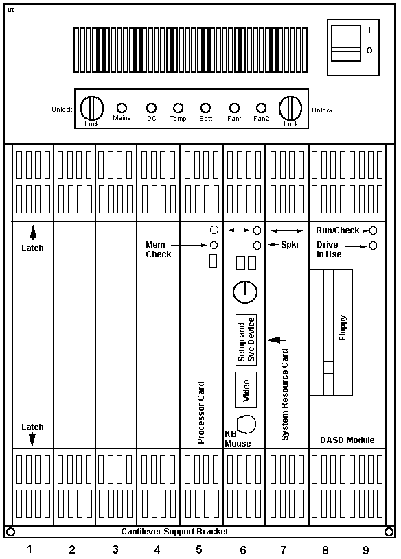
7568 Serial
Number Location
Took me a few months to notice it... Look on the left side of the
case half-way up. There is a slight depression along the inner edge. The
SN runs vertically. The SN is printed on a sticker that is the same color
as the case, so it won't stick out when you look for it.
Remove Front Panel
Rotate the two knobs to the unlocked position. Both knobs
will be horizontal in unlocked position. Note-
they rotate in opposite directions!
The panel will rotate on it's tabs on the upper edge. Once the panel
comes out to about 45 degrees, pull down and the panel will unhook itself
from the compartment.
Remove Top
Panel
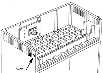
Pay attention! The top can be easily removed IF you push in
the catches in the front sides of the system. Stick a screwdriver into a
slot and push the catch inward while lifting the top panel up. Do the other
one. Once released, the top panel will pivot up and to the rear. If you try
to remove the top panel any other way, you may snap off the small pivot points
along the rear edge of the top cover.
Remove Shrouds
Notice the serrated areas on the inner side of the latches.
Push inward on the latches to release them. Now hold the latches and pull
out.
Insert Shrouds
WARNING! Do not install a shroud that
has an empty inteposer in it!
Hold the two latches horizontal while you slide the shroud
into the slot. Notice that the two backplane sockets are in the upper half
of the backplane. Lift up on the shroud so it guides on the top of the slot.
Now when it touches the back, you can let go of the latches because they
are within their retainers on the top and bottom off the enclosure.
Now let the shroud down slightly as you push it into the two
sockets. I push the shroud into the sockets by working on the top and middle
to rock it in. Compare the depth of the newly installed shroud with the
other shrouds. If they all look to be the same height vertically, and they
all are the same depth across the face, you have seated it. If you see the
shroud is sticking out, it probably needs to be reseated.
Now close the latches. Power up. If there is an error detected
or adapter not reported, power down and reseat it. Do NOT rush this! The two sockets in the shroud
are chock full 'o pins. God help you if you cram a shroud in and bend some
pins on the interposer!
Software
for the Gearbox
DOS, OS/2 (SE), (EE), AIX PS/2, Version 1.2.1 (Requires
PTF Level 210800, or later).
Use of OS/2 SE and EE Versions 1.2 and 1.3 will
result in a "system hang" problem when Control-Alt-Delete (C-A-D) is entered.
If C-A-D is entered, the system must be reset or powered down and restarted.
This is the same as on the previous C40 system.
GEARBOX Language Extensions are available for various
operating systems. Language Extensions provide the ability to take full advantage
of the unique error notification and orderly shutdown/startup capabilities
of the GEARBOX Model 800 system.
Available products are:
o GEARBOX Language Extensions for PC DOS
o GEARBOX Language Extensions for OS/2
o GEARBOX Language Extensions for AIX PS/2.
Interposer Cards
Installation of supported PS/2 form factor Micro Channel adapters
in the GEARBOX Model 800 system require the use of the applicable interposer
card to interface with the system backplane. Available interposer cards
are feature numbers 6224, 6225 and 6875.
16-Bit
Micro Channel Adapter Interposer (#6224)
The 16 Bit Micro Channel Adapter allows the plugging of selected
16 bit Micro Channel cards with a PS/2 form factor into the GEARBOX Model
800 Backplane.
16-Bit
Micro Channel Video Adapter Interposer (#6225)
This 16 Bit Micro Channel
Video adapter is required for installing the Display Adapter 8514/A (#4054)
in the system.
32-Bit
Micro Channel Adapter Interposer (#6875)
Support for the XGA Display Adapter/A (and for all other adapters
that exclusively use 32-bit slots) requires the use of these adapters. Using
a 16-bit Interposer may lead to functional problems related to a specific
adapter's use of a memory block above 16MB. Adapters that require 32-bit
slots should be used only with the 32-Bit Micro Channel Adapter Interposer.
32-bit Micro Channel adapters that can be installed in either
16- or 32-bit slots may have improved functional performance if they are
installed using a 32-Bit Micro Channel Adapter Interposer.
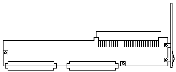
16-bit
ISA Adapter FRU 16F2527XM
From my secret agent out west, David Beem

The ISA adapter fits into J2 (AMP #645405-1). The bracket on the
adapter extends upward past the top of the image. P1 and P2 are similar
to the sockets used on 8580 memory cards. They are AMP 532505-1. There
are NO ICs whatsoever on this adapter.
Tony sez "It's G-R-R-R-E-A-T! (well, not exactly)
Looks like it needs to find a 16 bit shroud/carrier so it
can do something other than look pretty. I've got a bunch of the 32
bit ones, but they're the wrong answer here...
Also be aware that this adapter gizmo isn't a universal ISA/MCA
bridge device. Only a limited subset of ISA cards will work properly
with it. Gotta be a pretty dumb card not doing anything fancy (i.e. be able
to coexist with MCA). Something with a few I/O ports and not much
else would be a candidate. It really existed only so people
could use things like their old ISA A-D/D-A cards and things like that.
It's the only one I know of that IBM shipped. There
may have been some other lab prototypes somewhere that never made it out
the door. There was LOTS of weird shit floating around Boca that never
saw the light of day for one reason or another.
NOTE:
o Refer to the list of PS/2 and other adapters that are supported on this
system. The 16 bit Micro Channel Adapter must be used to install any supported
feature card in the Model 800, except for those that are in the GEARBOX
form factor.
o PS/2 adapters should not be installed in the slot #9 position. This is
due to limitations with setup and diagnostic code recognizing such adapters
in that position.
NOTE: PS/2 adapters should not
be installed in the slot #9 position. This is due to limitations with setup
and diagnostic code recognizing such adapters in that position.
Installing Adapters into Shrouds
WARNING If an adapter is installed
and operated without being secured in an adapter cradle, it may seriously
damage the card and the system unit.
Ed. My bet- if a card pulls partway
out of an interposer (say a SCSI adapter while you are trying to attach a
SCSI cable to it) then it might not be good.
To ensure proper airflow, remove
the Air-Blocks from the top of shrouds in which adapters will be installed.
Adapter Cradle
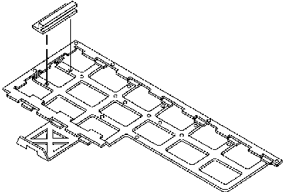
This secures an adapter within a shroud. The cradle
has mounting holes that fit on mating pins from the shroud. To get one,
you will probably have to Open A Shroud
Prepare
Interposer
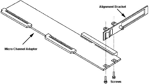
Use a standard screwdriver to remove both screws.
Connect Option to Interposer
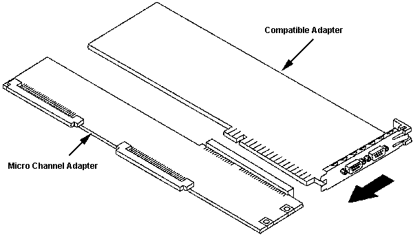
Insert Tabs Around Thumbscrew
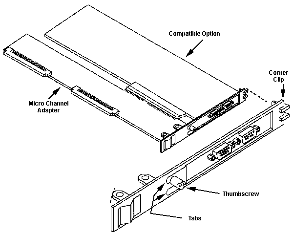
Loosen the thumbscrew on the alignment bracket. Position the tabs
around the thumbscrew. Press the card onto the alignment bracet and push the
alignment bracket up towards the corner clip. NOTE
The alignment bracket MUST be under the corner clip! Tighten the thumbscrew.
If the corner clip is under the alignment bracket, it will
bend the bracket and make it harder to slide the tabs under the thumbscrew.
Trust me.
Reattach Alignment Bracket to Interposer
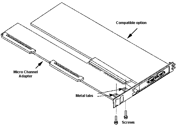
Align the metal tabs with the holes on the interposer. Reinstall
the screws. You may have to flex the alignment bracket to get the screw holes
to line up.
Insert Interposer into Adapter Cradle
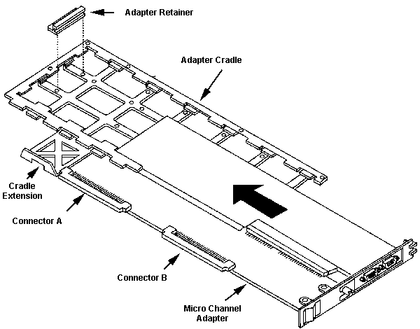
Slide the adapter and interposer under the tabs on the adapter cradle.
Make sure the cradle extension is between Connectors "A" and "B". Snap the
interposer onto the cradle extension between the connectors. Move the adapter
retainer to the appropriate position on the adapter cradle (depends on the
adapter length- full or half). Insure that the end of the card is in the
adapter retainer slot.
Open Shroud
Pry Up Shroud
Cover
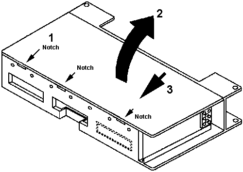
1. Insert a coin into notch and twist. Work along edge until cover is free.
2. Lift up on rear edge. 3. Slide cover rearward and out of the slots on
the front edge of the shroud.
Though I just grab the cover at a corner and pry it open.
Remove Air
Block
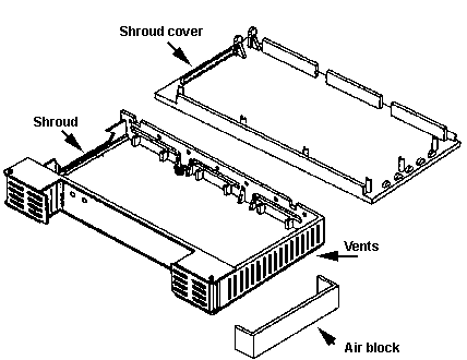
Air Block
The air block is a strip of paper that is inserted into the
outermost grille openings on the top of an unpopulated shroud. It keeps
the airflow from passing through the unused shroud, and instead, forces
it through the populated shrouds.
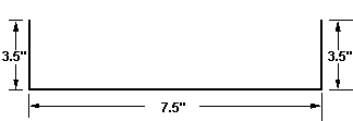
The Air Block is a "U" made of paper about the heaviness of
a manila folder. The strip is 1 1/16ths inch wide, 14.75" long, with scores
at 3.5" from either end. The center of the "U" is 7.5" wide.
Install Interposer Into Shroud
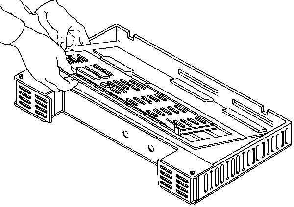
Make sure the alignment bracket is outside of the shroud.
Lower assembled interposer/adapter combo into place on the seven alignment
pins.
WARNING Make sure that components
on an adapter are not damaged when replacing the shroud cover.
Install
Shroud Cover
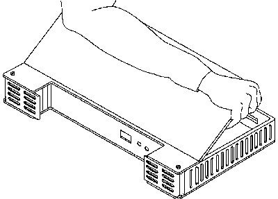
Align the tabs on the front edge of the cover with the front edge
of the shroud. Lower the rear edge of the shroudinto place and press it down
until it clicks into place.
GEARBOX MODEL 800 (7568-C40)
Intel 80486DX-25 processor card which can be
used to upgrade earlier models. The C40 supports the 4MB memory module and
320MB Small Computer System Interface (SCSI) disk drive. The C40 supports
attachment of the PS/2 3.5-inch Rewritable Optical Drive in the PS/2 SCSI
Storage Enclosure.
Attachment support for the PS/2 3.5-inch Rewritable
Optical Drive in the PS/2 SCSI Storage Enclosure requires that GEARBOX Model
800 systems shipped from IBM before December 1990, have the PF1193 BIOS
and Reference Diskette Upgrade installed.
LIMITATIONS:
OS/2 LIMITATIONS The following levels of OS/2 require
special consideration on the 7568-C40, with respect to the Control-Alt-Delete
keyboard entry:
o OS/2 Standard Edition, Versions 1.2 and 1.3
o OS/2 Extended Edition, Versions 1.2 and 1.3.
Use of Versions 1.2 and 1.3 of these products will
result in a "system hang" problem if Control-Alt-Delete (C-A-D) is entered
through the keyboard. C-A-D should not normally be used with the GEARBOX
Model 800. The key switch "Reset" position is provided for this purpose.
If C-A-D is entered, the system will have to be powered down and restarted,
or the key switch can be used to reset the system.
Machine Type 7568 -- Installation and Operation
Model C40 Guide, Three Port Cable (with ordered Assembly,
RFI Filter Kit,
No DASD Content 6551 N/C
One of the following IBM installed DASD content
alternatives may be ordered with the system order, at the listed additional
charge:
120MB SCSI Fixed Disk Drive (3) 6546 $ 3,500
320MB SCSI Fixed Disk Drive (3) 6547 5,500
The following are available for customer installation
on the GEARBOX Model 800:
80486 Processor Card Upgrade Kit 6543 $ 3,500
7568 Attachment Support for PS/2 Rewritable Optical
Drive PF1199 N/C
GEARBOX MODEL 800 (7568-040/150)
o Micro Channel (TM) Architecture with a 16/32 Bit
Bus
o Intel 80386DX-25 Processor with 32KB of Cache Memory
o 4MB or 8MB Base Memory Standard (Model Dependent),
Expandable to 8MB on the Processor Card (All Error Correcting Code Memory)
o 120MB SCSI Drive, with 0.5MB of DASD Cache Memory
on the Disk/Diskette Adapter Card (Standard on the Model 150, second 120MB
Disk Drive optional)
o Supported by IBM PC DOS (Version 3.30/4.0) and
OS/2 (R) (Standard Edition (SE) Version 1.1/1.2 and Extended Edition (EE)
Version 1.1/1.2)
o Battery Backup with Orderly Shutdown Capability
o 300 Watt Power Supply with DC Voltage Start-Up/Operation
Capability
o Integrated VGA Graphics, Serial/Parallel Ports
and Keylock
BASE SYSTEM
The GEARBOX Model 800 supports the PLANT FLOOR SERIES
(TM) Distributed Automation Edition (TM) products and related application
programs.
Integration of many functions on the
standard system cards leaves a higher number of slots available for customer
use (up to seven on the Model 040).
The GEARBOX Model 800 is based on an Intel 80386
microprocessor, operating at 25 MHz, and supports an optional 80387 Math
Co-Processor. The base memory is 8MB on the Model 150, or 4MB (expandable
to 8MB) on the Model 040. In addition, the Model 800 will support the 0-16MB
Extended Memory Adapter (#6345). All memory is Error Correcting Code (ECC).
Performance is further enhanced through 32KB of Cache Memory on the Processor
Card, a 120MB SCSI Disk Drive with 23ms access time, and 0.5MB of DASD Cache
Memory on the Disk/Diskette Adapter Card. A second 120MB Disk Drive is an
optional feature.
The Disk/Diskette Adapter Card also contains an
external SCSI interface for customer use. Use of this interface requires
that the customer provide a software device driver for interface to the intended
operating system. No such software device driver file is provided with the
system.
The GEARBOX Model 800 is supported by IBM PC DOS
(Version 3.30/4.0) and OS/2 (SE Version 1.1/1.2 and EE Version 1.1/1.2)
operating systems.
Language extensions for PC DOS and OS/2 will be
available in March of 1990, to take full advantage of the unique error notification
and orderly shut-down/start-up capabilities of the system.
Five IBM personal computer software languages are
supported:
o BASIC Compiler/2 (TM)
o C/2 (TM)
o FORTRAN/2 (TM)
o Macro Assembler/2 (TM)
o Pascal Compiler/2 (TM)
Two configurations of the GEARBOX Model 800 are
available. The configurations and brief content summary are as follows.
MACHINE TYPE 7568 MODEL 040
o Frame and Backplane
o Power Supply (300 Watts), autoranging, with function
indicators
o Processor Card with 4MB of ECC memory (expandable
to 8MB using 2MB Memory Expansion Kit, #5213), 32KB of Cache Memory, and
80387 Math Co-Processor socket
o System Resource Card w/integrated VGA, serial/parallel,
CMOS memory, and real time clock
o Keyboard and cable
o Card Shrouds with indicator windows (empty in seven
slots)
o Installation and Operation Guide with Diagnostic
Diskette.
NOTE: Initial set-up and loading of diagnostic software
on the Model 040 requires the use of the Set-Up and Service Device (#6230).
MACHINE TYPE 7568 MODEL 150
o Frame and Backplane
o Power Supply (300 Watts), autoranging, with function
indicators
o Processor Card w/ 8MB ECC memory, 32KB Cache and
80387 Math Co-Processor socket
o System Resource Card w/integrated VGA, serial and
parallel, CMOS memory, and RTC
o Keyboard and cable
o Disk Module (Disk/Diskette Adapter Card, with 0.5MB
DASD Cache Memory and Shroud)
o 120MB SCSI Disk Drive (a second 120MB Drive feature
is available)
o 1.44MB Diskette Drive (3.5-inch)
o Card Shrouds with indicator windows (empty in 5
slots)
o Installation and Operation Guide with Diagnostic
Diskette.
OPERATING SYSTEM STATEMENT OF DIRECTION: IBM intends
to provide a future Advanced Interactive Executive PS/2 (AIX (TM) PS/2)
operating system enhancement that will support the GEARBOX Model 800.
The GEARBOX Model 800 supports the following previously
announced features. All these feature cards require one of the Micro Channel
adapter features (#6224 or #6225) for installation, except the 0-16MB Extended
Memory Adapter (#6245).
DISK MODULE (#6222): The Disk Module allows for adding DASD to a Model 040. The Disk
Module consists of a double-wide shroud and a Disk/Diskette Adapter Card,
to be plugged into the Model 040 frame in place of two empty card shrouds.
The Disk/Diskette Adapter Card contains 0.5MB of DASD Cache Memory, and
supports up to two 120MB Disk Drives and a 1.44MB Diskette Drive installed
inside the shroud.
The Disk/Diskette Adapter Card also contains an
external SCSI interface for customer use. Use of this interface requires
that the customer provide a software device driver for interface to the intended
operating system. No such software device driver is provided with the system
or feature.
120MB DISK DRIVE (#6223): The 120MB Disk Drive is the same as the drive that comes standard
on the Model 150. The 120MB Disk Drive can be used along with the Disk Module
to provide a disk drive on the Model 040, or can be added to the Model 150
to provide a total of 240MB of Disk Drive capacity.
1.44MB DISKETTE DRIVE (SLIM-LINE)
(#6229): The 1.44MB Diskette Drive is the same as that which comes
installed on the Model 150. The 1.44MB Diskette Drive can be used along with
the Disk Module (#6222) to provide diskette function on a Model 040. The
Model 150 is limited to one diskette drive and cannot accept the 1.44MB Diskette
Drive in addition to the already installed device.
CARD SHROUD (MACHINE TYPE
7568) (#6530): This Card Shroud is the same as those that come
standard on the system. The Card Shroud permits installation of adapter
cards in extra shrouds for immediate insertion in a GEARBOX Model 800 system,
without having to open an installed shroud/card assembly for replacement
of the card in the shroud. The Card Shroud could also be used to fill the
open positions if the Disk Module were to be removed from a Model 150 system
(two Card Shrouds would be needed).
NOTE: The Card Shroud (#6530) is not compatible
with the IBM 7552 Industrial Computer Processor and System Resource cards,
due to different locations of openings in the shroud for LED indicators.
The GEARBOX Model 800 supports the following IBM machine types:
o 7544 Industrial Graphics Display
o 7554 Industrial Graphics Display
o 7525 Data Collection Terminal (PC DOS operating system only)
o 7527 Data Collection Terminal (PC DOS operating system only).
9595
Main Page
|


