|
8573 Power
Power Supply
Remove PSU (P70 and P75
similar)
Open PSU
Remove PSU
Switch Guard
Remove
PSU Switch
Fuse
Metal Screws to Reassemble
PSU
Power Supply Checkout (Square
plug pinout)
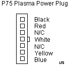
Plasma Screen Power Plug Pinout
(3x4 connector plug)
Power Supply Fan (Remove/Install)
ECA 068 (Modified P70 Bus Riser)
Modified Bus Riser Outline
ECA104 (Copper Tape on P70 PSU)
Copper Tape and RFI
Trivia)
P70 Trivia (applies to P75 some)
The system I am using sometimes refuses to start after power-on without
any display or beep symptom. After several power on-off eventually it starts.
Any idea???
From Peter
Looks like a slightly buggy power supply -or- systemboard.
The PSU is a little sensible against aging and overheating after many years,
because it is a known "dust collector". The PSU fan sits awkwarly mounted
over the PSU and only blows half (or less) through the PSU, which causes
dust particles to stay in the PSU. I would recommend that you remove it
from the machine and give it a good blow with a compressor and air-nozzle
to get out the dust bunnies from it. Make sure the fan is in working order.
Power Supply
Some P70 were upgraded with the P75 PSU.
P70 85W/.2kva
P75 P/N 64F8796, FRU 64F8798 100-240v 3.0A 50-60Hz Output ??W/.35kva
General impression of P75 PSU- pretty well built for a PSU with
a plastic case. The thin metal shield is only for EMI and it is quite thin.
The layout of the internal components is fairly open. Which certainly helps
when you are trying to blow out the dust bunnies.
The heat sinks are 3/32" COPPER. The only discoloring
on the main PCB was below the resistors R030 and R033 (56ohm, 5%, 2W wirewound).
I looked at the traces on the bottom of the PSU, and they weren't burnt.
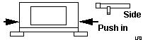
Remove Power
Supply
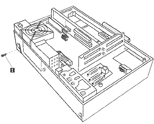
Remove the green/red wire and the ground strap from the
left of the fan. The forward mounting screw is in the black foot underneath
the rocker switch.
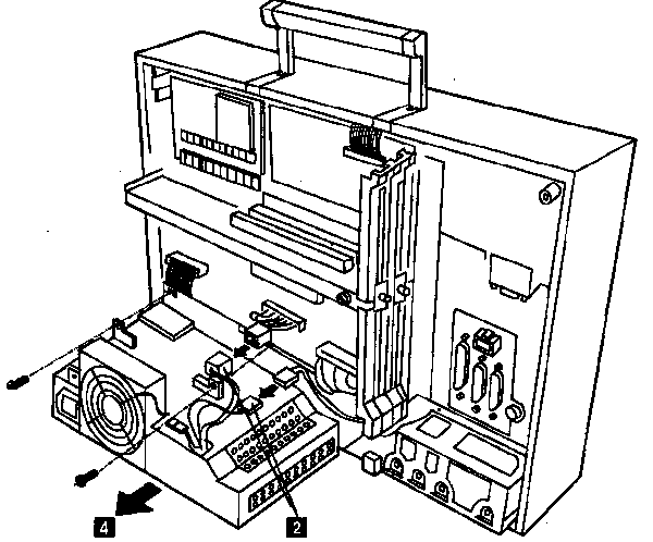 #2 Use the latch
on the side of the square, white power plug to unfasten it. Disconnect
the small, black plug for the fan. Use diagonal cutters to remove both
the nylon wire ties holding the black tubing on the plasma screen power
plug. Work out the kinks and pull the tubing towards the PSU. Squeeze the
tabs on the ends of the black power plug to unfasten it. #2 Use the latch
on the side of the square, white power plug to unfasten it. Disconnect
the small, black plug for the fan. Use diagonal cutters to remove both
the nylon wire ties holding the black tubing on the plasma screen power
plug. Work out the kinks and pull the tubing towards the PSU. Squeeze the
tabs on the ends of the black power plug to unfasten it.
NOTE: On the P75, the floppy cable
is attached to the PSU. Easier to just cut the barbed retainer, then use
a nylon cable tie to fasten it.
#3 Unscrew the retaining screw from both sides of the fan (white plastic
webs that come up from the PSU, mounts directly
to the P75 case).
#4 NOW you can pull the power supply straight out. Trust me, it's
so much easier when the front screw is not threaded into the PSU... I found
that opening the floppy and pushing down on the power switch allowed me
to easily pull the PSU out.
Opening Power Supply
First, drill out the rivets. Next, take out all the screws,
including the black security torx for the fan shroud (P75
only) and the ones used to attach the ground(s) on the left of the
PSU. You can't remove the top metal shield unless those screws are out!
Remove the power switch guard .Pop the
top of the metal shield off. Use a knife or a small standard screwdriver
to gently pry the flange over the catches. You will have to pull up on
the screw retainers that are on the top of the mounting flanges
.
Remove the top plastic half. This gives you access to the entire inside
of the PSU. You can stop disassembling the PSU and clean it.
IMPORTANT! Notice that the part
I marked as "AC Plug Frame" is now only held on by the wires out of the
back of the AC plug. On the P75 / late PSU, you can detatch the AC Plug
Frame by looking under the black tubing covered ferrite and squeezing the
top half of the white plastic plug. The entire AC Plug Frame will now be
free.
With the AC Plug Frame either removed or just swung away from the PSU,
you may now pull the bottom half of the metal shield off.
NOTE! To reassemble the PSU, the
bottom half of the exterior metal shield goes between the AC Plug Frame
and the plastic frame! It sort of fits the other way, but them the rivet
holes WILL NOT LINE UP.
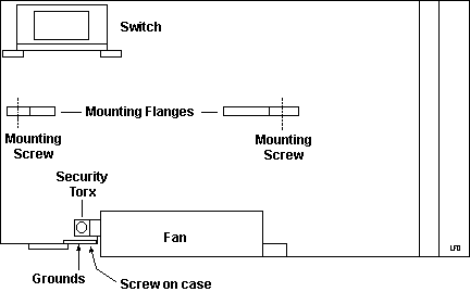
Remove Power
Switch Guard
Far simpler than it looks. Get a small jeweler's screwdriver.
On the underside of the switch guard, there is a small cutout on either
side. Stick the screwdriver inside the cutout and press the latch inward.
Pull up on that side of the guard so the latch is loose from the PSU frame.
Repeat on other side. Now with both latches loose, pull up on guard.
Remove Power
Switch
To pull the main PCB out, you must remove the power switch
(ALPS SDT-7, 5A/80A250V~). Carefully remove the two mounting screws. Be
aware that the mounting posts are darned near ten years old, they're fairly
thin, and they twist when you turn the screw too fast. Don't complain to
me if you snapped one off, I haven't any spares.
Fuse
5A 250V~ Marked SOC SD4 D250V5A. Please remember if the fuse blew,
it had to be due to SOMETHING.
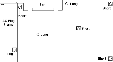
Metal
Screws Used to Reassemble PSU
After you drilled and pried everything open, you have to put
it back together. Get six #8 3/8ths" metal screws (called Pan Heads). Not
perfect, but they hold good enough for what we're doing.
NOTE! For the two screws on the
Power switch end (under the floppy port) you MUST
grind them down by 1/8th" or they WILL bottom out against the plastic PSU
frame.
Power Systems Checkout
To check the power supply voltages, do the following:
Note: If you can't power-on the
computer, the hard disk drive motor-start jumper might be on . Remove the
motor-start jumper.
1. Power-off the computer.
2. Unplug the two power-supply connectors.
3. Power-on the computer and check for the voltages listed below.
If the voltages are not correct, check the power cord
for continuity.
If the power cord is good, replace the power supply.
P75 Rectangular Plug
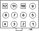
12 White
11 20GA Black
10, 9, 8 18GA Black
7, 6 N/C |
5, 4, 3 Red
2 Orange
1 Blue
0 |
Vdc Min Vdc Max Ground () Pin
Positive (+) Pin
+4.8 +5.2
6, 7, or 8 3 ,4, or 5
+11.5 +12.6
6, 7, or 8
2
-11.0 -12.9
6, 7, or 8
1
Pin positions 6 and 7 are unpopulated.
Plasma Screen Power
Plug Pinout
System Unit
Fan
It is a Matsushita Panaflow DC Brushless fan, Model FBK-09A12L,
DC 12v 0.1A
Remove P70
PSU Fan
For the P70 / early PSU,
there is no metal bracket over the fan. Instead, there are two black Torx
in the bottom two holes.
Remove/Install
System Fan, P75 / late PSU
You will need a T-10 security Torx. Unfortunately, you
need to get at the rear of the fan cage to get at the screws. If you don't
want to disassemble the sytem, use a 1/4" drive ratchet and a hex bit adapter
(assuming your security torx bit is a hex insert) to remove the two screws
in the top two holes.
Now pull the top outer edge out. Notice that the fan will
pivot on the two white pivots at the base of the power supply. Carefully
pull the power cable throgh the fan cage (you will have to turn the power
connector to fit thru the opening).
Personal opinion- I noticed
that the factory routing of the fan's power wires routed them through the
cutouts in the thermoplastic impeller housing. But notice that the right
fan cage mount for the right screw extends past that cutout, thereby allowing
you to tighten the fan housing against the extension with the wires between
them. Not a good design. Fix- I pulled the wires out of the cutout and
ran it down the side of the housing. There is enough room between the side
of the fan cage and the fan housing for the wires to fit without being
crushed.
System Unit Fan:
A non-functioning fan can cause heat to build up resulting in
intermittent problems. If the fan is not running, replace the power supply.
ECA068
Failure to load AIX, UNIX, or ZENIX. Indicates a
problem with the 8573 Models 061 or 121
where it would hang when trying to load AIX, UNIX, or ZENIX.
If your not doing any of these,
don't worry about it.
MACHINES AFFECTED:
8573, Model 061, S/N Below 50000
8573, Model 121, S/N Below 50000
NOTE: On a 8573-121, SN 1065064,
the bus interface assembly lacked the big electrolytic can.
P/N 56F9047, FRU 56F9101, but had the copper tape on the PSU.
I noticed slight wavering in the characters on screen in text only.
On an 8573-121, SN1031526, the bus interface assembly
has the big electrolytic can. FRU
65X1567. The image is rock steady in text mode. Both riser cards
are silkscreened with
iGH0256DA, 65X1308.
Modified Bus
Interface Card
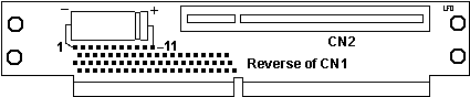
C1 1,000uF 16v, 85c Electrolytic
capacitor
CN2 16-bit MCA Socket (faces
down)
CN1 32-bit MCA Socket (faces
top)
The mod riser has the capacitor glued directly to
the riser. The negative lead is soldered to the top left pin from CN1,
the positive lead is soldered to the eleventh pin from the top left.
Both of the P70 risers that I have (one mod, one stock)
have the teeny SMD capacitor and
resistor to the end of CN2.
ECA104
-diskette or disk errors/hangs, loading/reading.
Indicates an RFI problem with the P70's that
caused intermittent drive failures during reading and writing.
Basically, the fix was to insulate part of
the power supply with 1/2" wide copper tape to prevent RFI leakage.
There was two seperate
pieces of copper tape- one the full length of the front horizontal
seam, the second about 1" long on
the seam from the corner of the ventilated end over to the long
piece.
There is a quick way to check to see if you need
this ECA, if you are familiar with opening up
your machine. Open up the back of the machine and check the bus
interface card, P/N 65x1567,
for a 1000Mf capacitor installed on the bottom of the card. If
you have this capacitor then you don't need ECA068. The capacitor apparently
helps eliminate data transfer noise that can prevent the loading of multitasking
operating systems.
Technical
Trivia on Copper Tape
Don Hills wrote:
The copper tape is relatively expensive and has
to be manually (expensively) applied. To justify
using it, they would have discovered significant RFI leakage
from the joint in some of the supplies. A long, thin slot makes an effective
antenna for wavelengths similar to the slot length. You need effective
bonding of the two metal surfaces all along the joint length. They may
have tested OK when new but failed testing after the surfaces corroded
slightly in service. They probably discovered it while chasing the RFI
problem with the diskette drives.
To understand how a hair-thin slot can radiate more
RF than a "swiss cheese" perforated panel, consider a half-wave dipole
antenna (VHF TV antenna is a good example). It's a rod of metal surrounded
by air, with the feed line connected in the middle. Now reverse the components
and you have a "rod" of air surrounded by metal. Connect the feed wires
to each side of the slot at the
midpoint and there you are again - a half wave dipole. (The electromagnetic
theory is actually a bit
more involved than that, but it illustrates the concept).
9595 Main Page
|