9585 K, N Models
9585rf.exe Reference v1.32
23 Feb 94
9585rd.exe
Diagnostics v1.30 23 Feb 94
F/W SCSI Adapter
Firmware Upgrade 7.1
193-295 SERVER 85 433 AND
466 -- New Models
9585 Power (same as
95, but 288W)
K/N Planar
Blown Nichicon
Capacitors!
85 K/N Ports
Problems
Installing OS/2 on 9585 (2.x and Warp)
L2 Cache
Odd bracket in Basil's ONT
(why is a fan power bracket there, see the plug
holder?)
BIOS Upgrade-
"F5JW15UK" If you know where it is, tell ME
! (link fixed 22 Jun 06)
ADF sections
K/N Planar 64G2401 / 82G2481
(DX2), 64G2405 (DX),
BH1 Battery
Holder
CR1 LED
for F/W .
F4 Keyboard Fuse
F12, F13, F14, F15 PTC Resistors
F16, F17 SCSI Autoterm?
J1,3,4,7,10,12
32 bit MCA Slots
J2 Operator Panel
J5 JMP1 Password
Override
J6 JMP2
Privileged-access
J8 Floppy
J9 32 Bit Slot
(BVE)
J11 32-bit
Slot (AVE)
J18 JMP5
Remote Flash
J27 Keyboard
J28 Mouse
J201 Parallel
J203 Serial
J452 External C68 FW
SCSI
J460 Internal C68 FW
SCSI
J463 JMP7 SCSI
Boot 0- Allow
J469 JMP4 Remote
Power On
JMP3 LogicLock
JMP6 ServerGuard
R462
Temperature Sensor? |
U2 Dallas
DS1585S RTC
U9 14.3181 MHz
Osc
U16 82077SL
Floppy Controller
U22 24.0000
MHz Osc
U49 10G7808
DMA Controller
U65-G
10G4672
U77 22.1184
MHz Osc
U84
71G2540
U97
71G2539
U134 61G2444
Int SCSI Cntrlr
U135 61G2444
Ext SCSI cntrlr
U136 Sony
CXK581001M-70L
U138
Sony CXK581001M-70L
U139 61G3930,
SCSI BIOS, Even
U140 61G3929,
SCSI BIOS, Odd
U142 AMD
N80C186-20
U146 40.0000
MHz Osc
U151 61G2323
MC Bus interface
U179 L2 cache
connector Lacuna
U188 Socket 3
LIF Straight 5v!
U198-PAJ
69G1212
U199-PG
69G1204
U205 66.0000
MHz Osc
1 |
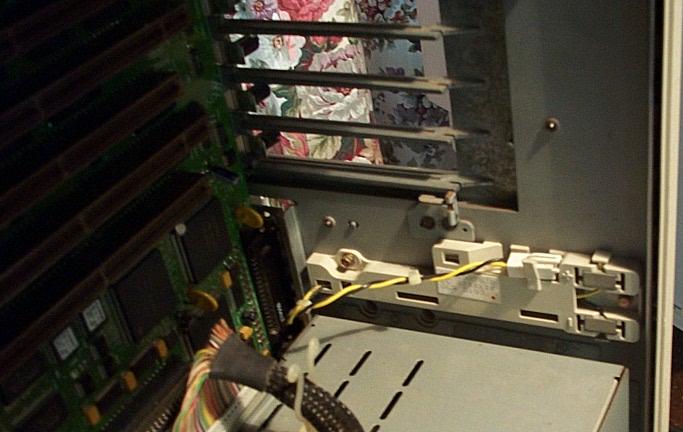
Blown Nichicon Capacitors!
My planar F/W adapter refused to respond to a
Controller Reset in Advanced Diags. It would not flash
to the C9 level of BIOS. What really plugged things up
was a Corvette controller in a slot could not format
an HD, because the planar SCSI had thrown an error and
the diags had flagged it.
I stripped the system down and started to blow
out the slots and around the chip leads with computer
duster (cheap brand from Staples). It was then that I
noticed the green on some chip leads and on top of the
planar. From experience, it was necessary to pull the
planar in order to wash the corrosion off effectively.
First wash was with white vinegar and that really
cleaned things up. The next wash is with baking soda
so we neutralize any acidic compounds still on the
board.
Further investigation showed that ALL three Nichicon
10uF, 25v, 105C electrolytic capacitors (N251) had
blown.
The three caps were:
C293 under U84
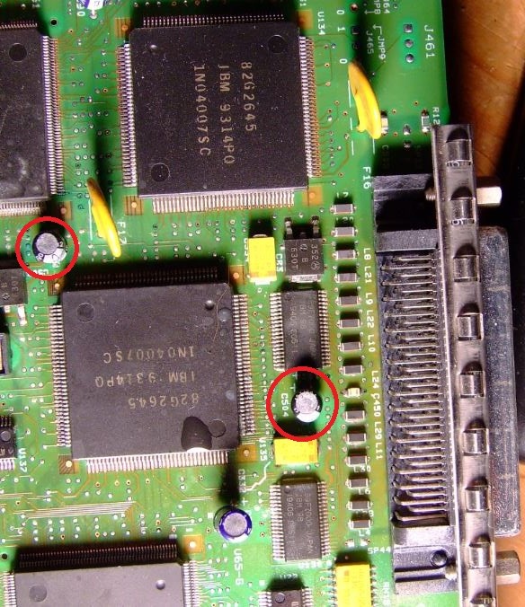
C503 by upper right corner of internal F/W connector.
C504 by U131
C293 on left lower corner
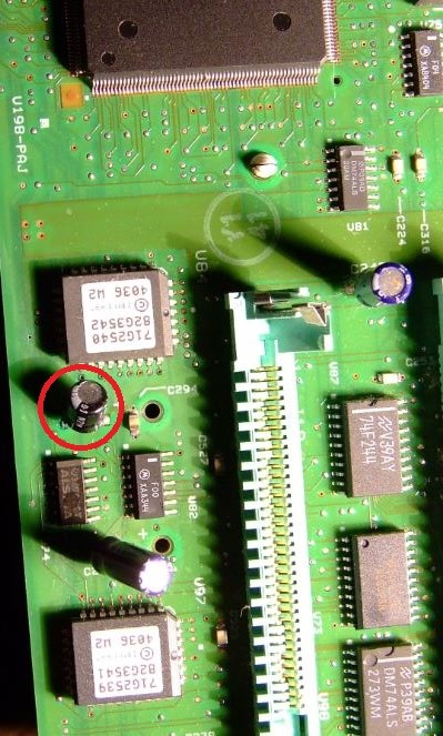
|
C503 and C504 by External SCSI port
|
Of the three,
C503 was the most significant because it is to the
upper left of U135. It managed to corrode some pins at
the upper left corner, and the PTC F17 made it a bit
cramped to apply the vinegar.
9585-K/N Ports
9585 K/N I/O Ports

COM
supports up to 345K
LPT is bi-di
parallel
SCSI is a
Fast/Wide
|
9585-K/N Operator
Panel
|
Reference v 1.31
on the -xXx?
Another word for the BIOS: Once you'd put the
inappropriate version of the Reference / Diags on an 85
and start for example OS/2 ... you could see really odd
effects. Putting the 1.31 code from the -xNx on a -xXx
result in a "speed cursor": a fast flashing icon on PM and
you cannot click that fast to do anything with the machine
anymore with using the mouse. You need to shutdown the
beast over the keyboard. The xxx.BIO files differ - and
these set the onboard timers to false base values. I had
that in '92 or '93 when customers complained about
inability to use their machines after "an update". They
used the 1.31 "just because it was there and had a higher
revision number". Without thinking and reading the DOCs as
it seemed.
Parity / ECC in System
Programs
The 85 can emulate ECC using parity SIMMs. This
is not worth it. Leave the Memory Detected setting in
Change Configuration to "Parity". Go to "ECC-P"
for more details.
System memory can be optionally expanded up
to 256MB using 32MB Parity SIMMS. 2MB to 32MB Parity
SIMMs are supported, INTERLEAVED ONLY. All 256MB are
addressable by Direct Memory Access (DMA). SIMMs must be
installed in pairs of the same size. speed, and type. {Ed. I have used the 32MB
EOS
SIMMs successfully. If you do, use the "Parity"
setting under System Programs. Remember, the ECC
function is performed on-SIMM so using ECC-P is
redundant at best].
Mixed Memory Sizes in K and N
Models
When a mixture of 4MB, 8MB and 16MB (or
larger) SIMMs are installed in the 9585-xKx and -xNx
computers, install the larger pairs in the lower
numbered connectors (A1/B1 lowest) and the smaller pairs
must be installed in the higher-numbered connectors
(A4/B4 highest), .
Parallel Port
Bidirectional with DMA support. 100KB/s max
supported speed.
Fast\Wide SCSI
The IBM SCSI-2 Fast/Wide busmaster controller
is integrated on the system board. It uses the same
chipset as the Fast/Wide SCSI. 40MB/s Data Streaming to
MCA bus (32 bit), 20 MB/sec on SCSI bus (16 bit).
Server85 - Sharing External
SCSI DASD fails
External SCSI DASD expansion shared between
two system fails when one of the systems is powered
down.
On the 9585 0N* the trace on the
solder (back) side of the planar running parallel below
resistor R351 must be cut. On the SCSI-2 F/W controller
the trace running next to C30 on the component side of
the card must be cut. This trace runs from the fourth
pin from the right on the bottom of the larger IC next
to the external connector.
They did not EC the planar due to the expected low
instances of this problem.
50 to 68 pin adapter
A 50 pin cardedge to a female 68 pin half pitch
Centronics is FRU61G3594. The female 68 pin socket is an
AMP part.
Can't Use >7 SCSI Devices
From John Poltorak
>How come your machines can always use 15 devices and
mine max out at seven?
From Peter
Q1: which internal
cable do you have ? The odd-colored woven double wire
cable with 50 pin connectors ? Or the "later" internal
Wide-SCSI cable with 68-pin plugs at the device ends
?
Q2: (results from
Q1:) which port on the internal adapter are you using ?
The 68-pin Molex (black plastic) directly on the board
or do you have the Molex-to-50 card-edge converter in
between ? If so - the adapter is switched into 8-bit
narrow mode and will take only 7 devices. You need to
use the 68-pin Molex without the converter to have
advantage of the 16-bit Wide mode. If you have the
converter attached to the Molex the external port is
also run in 8-bit mode as far as I know - and limits the
adapter to ... seven devices.
The planar F/W SCSI on the Server 85 is
*similar* to the "3 connector" F/W SCSI adapter /A
(8EFC) - but it differs a lot. The F/W card has a
separate 50-pin card-edge connector for the internal
devices - and using this connector with only "narrow"
devices does not afflict the ability to use "Wide"
devices on the external port - given that you use a
"wide" cable as well. You cannot use an internal narrow
cable and external narrow cable as well and hope that
you can adress 15 devices with that. This will not work.
As soon as you use an 8-bit cable you are cut to 7
devices on the planar F/W.
Enhanced security --
the Server 85 433 and 466 with LogicLock
and new tamper-evident, locking covers, Privileged Access
Password, selectable drive startup and support for
optional features (such as, the new Cable
Cover 4 and the Enhanced 2.88MB 3.5-inch Diskette
Drive with electronic eject) provide system security
exceeding C2 enabling requirements.
Remote power-on
feature that allows the server to be powered-on
remotely via an external modem, or from an internal
timer. Remote power-off can be achieved through software
control and is beneficial for running reports or
printouts remotely, during off-shift periods.
Unattended start mode The
Server 85 433 and 466 models can automatically restart
the server after a power failure and resume normal
operation, without operator intervention
Vital Product Data
(VPD) enabled for unique ID (model/submodel);
Type/model/serial number; Planar serial number;
Manufacturing ID; Planar FRU number; Planar part number.
A system administrator can view from the LAN the PS/2
Server 85 models that reside on the network, including
configuration. This function can also serve as a
security measure by confirming if unauthorized servers
are connected to the network.
Problems
Installing OS/2 on 9585 Computer (HERE)
From Joltin' Joe Kovacs
One of the following error messages is displayed at
Diskette 1 while installing OS/2 on an IBM PS/2 9585
computer:
* OS/2 Warp: OS/2 is unable to operate your
HD or diskette drive.
* OS/2 2.x: The system cannot find the
file 'A:\COUNTRY.SYS'.
The diskette-drive light stays on, and pressing
Ctrl+Alt+Del has no effect. The system must be turned off
and then turned back on.
Note: This problem
is particularly troublesome because at the first sign of
trouble during OS/2 installation, users remark-out (REM)
all unneeded drivers in the CONFIG.SYS file; for
example, BASEDEV=IBM1*.ADD. This should be a line of
action because the PS/2 9585 is a Micro Channel system.
However, if the statement BASEDEV=IBM1FLPY.ADD is
remarked-out, OS/2 installation will fail with one of
the above error messages.
Make sure the REM in front of
BASEDEV=IBM1FLPY.ADD is removed in CONFIG.SYS file. If
the line was deleted, restore it. If there are no other
problems, the installation will work.
L2 Cache
0Kx - 128kb L2 WB cache. 0Nx - 256kb L2 WB
cache.
Both use the same cache modules
as the 76/77 Lacuna planars.
Uh, Maybe Not
I tried a variety of L2 modules in my N. They all
failed (with POD and interposer) until I tried an IDT
256K WB module, 7MP6150. To my surprise, the Cypress OEM
P/N 06H3306 and P/N 06H3307 failed, either jumpered for
WB or WT. The failures were a continuous looping reboot,
or a black screen (with interposer).
0Kx and 0Nx
models are also:
1) Intel Pentium Overdrive
upgradable (socket is 19x19 LIF)
NOTE: The CPU socket is
right behind Bay #3. The original DX2-66 in my 85 had
about 3/8ths of an inch of the heatsink fins milled off on
the left side of the 486. If you use a POD (like me) be
cautious of trying to ram a 5.25 inch drive or CD into
that bay.... "It won't fit! @%#&!!! Bam! Bam!
Crunch!"
Without the interposer, the POD does not tolerate
any of the L2 cache modules I have, either IDT or Cypress
(IBM). I had to take out the cache...The interposer looks
like THIS
Details how to make your own are there, too...
2) SurePath BIOS,
upgradeable via "FLASH" EPROM (IBM never released an
upgraded BIOS.... My ONG has BIOS 00)
3) SCSI-2 F/W adapter (Oh
yeah baby! Oh, behave!)
4) Capable of 256MB w FPM
-OR- EOS [Ed. I have used both 256MB FPM and
EOS]
| System Board 486DX-33 w/SCSI |
61G2405 |
| L2 Cache 128KB (for 61G2405) |
61G4098 |
| System Board 486DX-33/66 w/SCSI |
61G2401 |
| L2 Cache 256KB (for 61G2401) |
61G4098 |
ADF
Sections AdapterId FEDF Built In Features
for 9585-K/N Planar
Num Lock
How the Num Lock key will be set when the
operating system is started. Please note that your
operating system environment might change the setting of
the Num Lock key. The normal setting of this
feature is <Off>.
<"Off">,
On
Display F1 prompt to access
System Programs
During startup, your system normally
displays a prompt that tells you to press F1 for access
to the system programs. If you wish to suppress this
prompt, change this to <No>"
<"Yes">,
No
Hands-off Configuration
[this is commented out]
Normally, when you add or remove adapters,
devices, or memory, you provide input to reconfigure the
system. If you change this setting to <Enable>,
;the system will attempt a hands-off configuration when
hardware is added ;or removed. No user input will
be required unless the default values cannot be used.
<
"Disable" >, Enable
Serial Port
The serial port can be assigned as Serial 1
through 16, or disabled. Standard COM
port interrupt levels are IRQ 4 for serial 1
and IRQ 3 for any other serial level.
<"SERIAL
1, IRQ 4">, many choices, Disabled
Parallel Port
The parallel port connector can be set as
Parallel 1through 4 or the port can be disabled.
<"PARALLEL
1">, 2, 3, 4,
Disabled
Parallel Port DMA Arbitration
Level
The parallel port connector can be set to
any one of the available DMA arbitration levels.
If the level selected is shared then other devices can
be set at the same level. If the level selected is
dedicated then only this device can be set to that
level. Select <Disabled> to use the port in
compatibility mode.
<"Shared
level 7">, 6, 5, 4, 3, 1, 0, Dedicated 7, 6,
5, 4, 3, 1, 0, Disabled
SCSI Address (ID)
ID of the built-in SCSI controller. Under
normal circumstances, select <7>.
<"7">,
6, 5, 4, 3, 2, 1, 0
SCSI I/O Address
I/O address of planar SCSI
controller. Normally, use <3540h-3547h>.
<"3540h-3547h">,
3548-354F, 3550-3557, 3558-355F, 3560-3567, 3568-356F,
3570-3577, 3578-357F, Disabled
SCSI DMA Arbitration Level
Arbitration level planar SCSI controller
uses to transfer data. Normally, select <Level C>
<"Level C">, D, E, 8, 9,
A, B, 1, 3, 5, 6, 7
Move Mode Support
Enable or Disable Micro Channel Subsystem
Control Block Move Mode for the built-in SCSI
controller. Under normal circumstances, select
<Enabled>
<"Enabled">, Disabled
Wait State Support
Enable or Disable Bus Master wait states
for SCSI controller. Normally, select <Enabled>
<"Enabled>, Disabled"
Selected Feedback Return
Exception
If the SCSI controller uses the MCA
Selected Feedback Return Exception feature.
<"Ignored>, Enabled
100ns Streaming Data Transfer
Support
SCSI controller supports 100ns Streaming
Data Micro Channel protocol, which provides better
performance on the Micro Channel.
< "Enabled">,Disabled
Target Mode
Target mode should be disabled only if this
system is sharing SCSI devices with another system and
there are more than 15 devices to be shared. Only
15 devices can be configured on the built-in SCSI
controller. When target mode is enabled, the built-in
SCSI controller appears as a processor device on the
other system and unless you have specialized software
that can communicate between the two systems through
these processor devices (peer-to-peer communication),
there is no advantage in having target mode
enabled. When target mode is disabled, the
built-in SCSI controller does not appear as a device to
the other system, and one more device can be shared by
the two systems. If your system is not sharing any
SCSI devices with another system on the built-in SCSI
controller, it does not matter whether you enable or
disable target mode. The normal default for this
option is enabled."
<"Enabled">, Disabled
SCSI Disconnect
Disconnect is a SCSI-bus procedure in which
a device logically stops communicating with the built-in
SCSI controller during certain operations and then
reestablishes communication with the built-in SCSI
controller when the operation is complete.
Disconnect should not be confused with the 'Presence
Error Reporting' option for a device in 'Set and view
SCSI device configuration.' If you are using an
operating system that is single-threaded and issues
commands to only one device at a time (such as DOS),
disabling SCSI disconnect might result in a slight
performance improvement. If your operating system
is multi-threaded (such as OS/2), disabling SCSI
disconnect will degrade the performance of the SCSI
subsystem. The normal default for this option is
enabled.
<"Enabled">, Disabled
Fast SCSI - External
Enabling Fast SCSI external improves
performance if you have one or more Fast SCSI devices
attached externally in one of the following
configurations :
1) One external SCSI device enclosure model 3511.
2) Up to three external SCSI device enclosures model
3510.
3) Any external configuration in which the SCSI cable
length does not exceed 3 meters. The normal
default for this option is disabled."
<"Disabled">, Enabled
Wide SCSI messages - External
The setting for this should be 'Enabled'
unless you have a Wide SCSI device attached to the
built-in SCSI controller through a narrow (8 bits wide)
external interface cable. Refer to the
documentation that came with the device and cable you
are using to determine whether it is necessary to
disable Wide SCSI messages. The normal default for
this option is enabled."
[ed. this changes if
the adapter terminates the high byte (disable). If you
have a 50 pin cable, disable wide messages]
<"Enabled>, Disabled
Wide SCSI messages - Internal
The setting for this should be 'Enabled'
unless you have a Wide SCSI device attached to the
built-in SCSI controller through a narrow (8 bits wide)
internal interface cable. Refer to the
documentation that came with the device and cable you
are using to determine whether it is necessary to
disable Wide SCSI messages. The normal default for
this option is enabled.
[ed. this changes if
the adapter terminates the high byte (disable). If you
are using the 50 pin edgecard adapter, FRU61G3594,
disable wide messages.}
<"Enabled">, Disabled
ADPItem 1 Processor
Type of processor currently installed on
the system board.
ADPItem 2 Bypass System
Programs on Error
When the power-on self-test (POST) detects
an error, POST normally starts the system
programs. If you want POST to start the operating
system instead, choose <Enable>.
Warning: Setting this to <Enable> could
result in a partially configured system when an adapter
or device is added. A partially configured system
may cause some operating systems and applications to be
inoperable."
ADPItem 3 Memory-Checking
Method
Method that the computer uses to check the
system memory, either parity or ECC (error-correcting
code). The ECC-checking method allows the computer
to continue to operate in the presence of single-bit
memory failures. Note:
If a bad-battery error (161) or a
configuration-integrity error (173) occurs, the
configuration will be reset to use the parity-checking
method.
9595 Main
Page
|