M-Motion Video Adapter
@80B3.adf M-Motion Video
Adapter
@80B3.adf Enhanced M-MVA [adds
monitor choice] date 2/10/90
191-037 Enhanced M-Motion Video
Adapter/A for the IBM PS/2
190-018 M-Motion Video Adapter/A
for the IBM PS/2
m-motion.exe
M-Motion 256 color driver Thanks, Dr. Jim!
mcontrol.zip
MMotion Media control for M-motion Adt
mmpmctr1.exe
MMotion MControl/2 for MMPM (1/2)
mmpmctr2.exe
MMotion MControl/2 for MMPM (2/2)
292-663
IBM M-Control Program/2 Ver 2.01
m-mvidad.exe
M-Motion Video Adpt. Software v1.02
m-mvidad.txt
Readme for m-mvidad.exe
M-MVA Base Card
M-MVA Daughter Card
Different Versions of
M-MMVA
M-MVA Cable Identities
M-MVA Cable Pinout
(DB37 to each connector)
Installation
Procedure
Attach
Monitor to M-MVA Cable
Systemboard
Video Termination
Terminator Pinout
for M-MVA
ADF (shared by old and new
M-MVA)
Thank Fred Spencer up in Maple Syrup Land (BC) for the
MMPM files.
M-MVA
Base Card
J1 12 Pin
Header
J2 80 Pin
Header
OSC1 18.000000
MHz Osc
U3 Valor
DL2086 20nS
U7 Altera
EPB2001LC
U21, U23
Cypress CY7C408A -25VC |
U22 Xilinx
XC3390 PP175C-5000
U25 NEC
D41256L - 85
U26-U31
Toshiba TC5242256AZ-10
U35 Xilinx
XC3390 PP175C-5001
U36, U37
Cypress CY93L422PC
U38 INMOS
IMSG176J-40 |
M-MVA
Daughter Card
J1 12 Pin
Header
J2 80 Pin
Header
P2 Solder Pads
for 26 Pin Header
U1 Phillips
TEA6300T
U9 Phillips
TDA4580
U11-U14 RET
(?) RF6609ANP -011
U16 Analog
Devices AD7547KP |
U17 Analog
Devices AD7870JP
U22 Phillips
SAA 9060P
U27 Phillips
SAA 9057A
U28 Phillips
TDA8709T
U29 Phillips
TDA8708T
U30 Phillips
SAA 9051 WP
Y1 24.576 MHz
Crystal ??? |
Different Versions
The M-Motion Video
Adapter/A (#1991, 95F1091) replaces original M-Motion
Video Adapter/A (#3487, 34F3087). Refer to Product
Announcement 191-036 [Ed.
can't find it].
M-MVA Cable
Identities
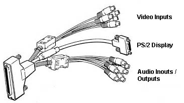
Video Input
(5 RCA plugs)
I/O Name
V1 Vid In
1
V2 Vid In
2
V3 Vid 3/Chroma2
VC
Chroma 1
CS Comp
Sync
|
PS/2 Display
(HDD15)
I/O Name
Pin1 Red
Pin2 Green
Pin3 Blue
Pin4 N/C
Pin5 VSync
Gnd
Pin6 Red
Gnd
Pin7 Green
Gnd
|
PS/2
Display
(HDD15)
Pin 8 Blue Gnd
Pin 9
N/C
Pin10
HSync Gnd
Pin11 N/C
Pin12 N/C
Pin13 H
Sync
Pin14 V
Sync
Pin15 N/C
|
Audio
In/Out
(6 RCA plugs)
I/O Name
1L Aud In
1L
1R Aud in
1R
2L Aud In
2L
2R Aud In
2R
OL Aud Out
L
OR Aud Out
R |
M-MVA Cable Pinout
Video Input Cables
(5 RCA plugs)
DB37 I/O Name
4 V1
Vid In1
23 V1 Vid
In1 Gnd
2 V2
Vid In2
21 V2 Vid
In2 Gnd
3 V3
Vid In3/
Chroma In2
22 V3
VidIn3/
Chroma In2 Gnd
1 VC
Chroma In1
20 VC
Chroma In1 Gnd
8 CS
Comp Sync
27 CS
Comp Sync Gnd
0
0
0 |
PS/2 Display Cable
(HDD15 connector)
DB37 I/O Name
6 Pin 1
Red
7 Pin 2
Green
5 Pin 3
Blue
Pin
4 N/C
29 Pin 5
VSync Gnd
25 Pin 6
Red Gnd
26 Pin 7
Green Gnd
24 Pin 8
Blue Gnd
Pin
9 N/C
28 Pin 10
HSync Gnd
Pin
11 N/C
Pin
12 N/C
9 Pin 13
H Sync
10 Pin 14
V Sync
Pin
15 N/C |
Audio In/Out Cables
(6 RCA
plugs)
DB37 I/O Name
19 1L Aud
In 1L
37 1L Aud
In 1Gnd
18 1R Aud
in 1R
36 1R Aud
In 1Gnd
16 2L Aud
In 2L
34 2L Aud
In 2Gnd
17 2R Aud
In 2R
35 2R Aud
In 2Gnd
15 OL Aud
Out L
33 OL Aud
Out LGnd
14 OR Aud
Out R
32 OR Aud
Out R Gnd
|
Installation Procedure
1 Copy @80B3.adf
to floppy, update Refdisk or System partition..
2 Install M-MVA in AVE slot
(16 or 32 bit). M-MVA uses base
video
from XGA or XGA-2
3 Connect all cables to PS/2,
but DO NOT CONNECT any cables to M-MVA.
All
setup screens will be visible and M-MVA palette
registers are correctly initialized.
4 Run Automatic Configuration and
save. Reboot and run system programs again.
Select Set
Configuration > Change Configuration. Choose 8515 for
better display quality.
Reboot system and run software
installation program.
Attaching Monitor to VGA Display
Connector
NOTE:
The PS/2 color display should be cabled to the VGA
Display connector (HDD15) cable after the M-MVA has been
installed and successfully configured.
System Board Video Termination
Whenever a color display is attached to the
VGA Display connector, the VGA Terminator plug MUST be installed in the
system board display connector. Otherwise, the PS/2 VGA
adapter will not recognize that a color display is
attached to the M-MVA, and all VGA and video output will
be displayed in monochrome (B&W). (Ed. Does this apply to a
Base Video adapter like the XGA-2?)
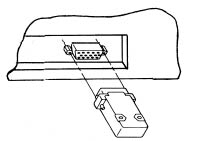
Terminator
for
M-MVA
From Brad Parker (out among the flat cornfields of
Iowa)
This is the terminator that came
with an M-motion adapter. I suspect that it would work
equally well with the ATi Gup or any other auxiliary video
card. Probably keeps the video drive amps on the unused
card from going into oscillation.
The terminator requires three 75 ohm 1/4 watt
resistors. As 75 ohms can be difficult at times to find,
rest easy in knowing that the originals have a 20%
tolerance, so any 5% tolerance or better resistor with an
impedance between 63 and 100 ohms should work.
The resistors are wired in parallel between each
color's drive pin and it's respective ground. In addition,
the terminator keys the monitor ID to 0 by having a jumper
between the 0 ID pin and digital ground. (Monitor Presence
Detect ID=0); which together with opens on Pins 4, 12, and
15 (MPDID 1, 2, and 3) ensures that the system thinks an
8512 or 8513 (640x480 analog color only) monitor is
attached.
Use a 15 pin male VGA connector and hood.
The component values are as follows: R1-R3 75 ohm 20%
1/4 watt resistor J1 Insulated 24 gauge single conductor
wire
Connect as follows:
Pin
Pin
1 ----^v^v^v^v---- 6
2 ----^v^v^v^v---- 7
3 ----^v^v^v^v---- 8
10 ---------------- 11 (shorted, in
words)
Note the original unit has shrink tubing
on the resistor leads-Not a bad idea. An alternate
technique would be to just plug in any old monitor on
the base video VGA output. Of course that takes up a bit
of physical desktop.
Description
The M-Motion Video Adapter/A is a full-frame
buffer that adds audio and video to the Personal System/2
system units with Micro Channel architecture. This
adapter is capable of receiving Composite Video (3 PAL
(R)/NTSC or 2 SVHS) and produces a corresponding video CS
output signal to synchronize the input video
sources. The CS output is fully compatible with CCIR
standards at line periods of 64Us and 63.555Us. The
CS output voltage is compatible with TTL levels,
terminated into 75 Ohms. Composite
Sync (CS) output is available to synchronize up to three
compatible video input sources at the same time.
Features and characteristics:
o Full control of digitized video via
M-Control Program/2 software. The digitized video images
can be sized, captured, stored, and recalled from
the PS/2 workstation.
o Full control of output video (contrast,
hue, brightness) via software. Output video and
the VGA text and graphics are interchangeable and can be
overlaid via software.
o Video output fully compatible with PS2 VGA
display connection and fully compatible with all high
resolution VGA modes (640 and 720 horizontal
pels). Limited support is provided with
low resolution modes (320 or 360 horizontal
pels). This adapter requires the Micro Channel
expansion card slot with video extension.
o The capability to produce stereo audio
output at high quality from two stereo analog audio
programmable inputs. The input line audio can also
be digitized and played back at FM quality levels. Full
control of audio output (volume, treble, bass, and
balance) is available via software.
080B3
"M-Motion Video Adapter/A" Same adf, some additions for new M-MVA)
pos[3]=XXXXX111b ; Allow readback of adapter rev
level [added to new adf]
Adapter I/O Address Range
<"Base
1300H", (1300-1339>, 3300 (3300-3339), 5300
(5300-5339), 7300 (7300-7339)
Adapter Interrupt
This adapter uses a hardware interrupt
which may be shared with another adapter, but for
maximum performance the interrupt should not be shared.
If it must be shared, share with the interrupt which has
the least activity. This adapter interrupts at a
rate of 50 to 60 times per second when enabled. NOTE: Some adapters label
interrupt 9 as interrupt 2. If another adapter is
using interrupt 2 and you choose interrupt 9, you will
be sharing interrupt 9 with that adapter.
<Interrupt
3> or 9
Display Type (New ADF)
Chose 8514 if you have an 8514 or earlier
display. Chose 8515 if you have an 8515 display
<"8514">, 8515
9595 Main
Page
|