9595A Planar
See 95 Common Devices for installing
drives, memory, opening and closing the case.
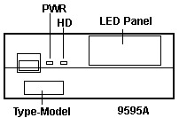
Operator Panel Information (Audio Stage,
HD LEDs,
95A Op Panel Multimedia Port
Pinout
95A Compatible
Complexes
JMP 6 Remote Maintenence Processor
Hacking a 95A Planar
into a 8595 Case
IEEE 1284 Parallel Port
(LPT A, bottom port)
LogicLock
Power-On Features
(Wake-On-Ring,
Kickstart, Wake-Up)
ADF Sections (PE4FE.ADF)
The most advanced
microchannel planar. There are none higher.
95A Ports
95A Ports
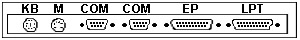
COM ports are 345K capable
EP is an ExpressPrint parallel
port
LPT is a standard parallel port |
95A Operator Panel
|
95A
Compatible Complexes
Sorry, folks, but personal experience (supported with that of
others, BTW) proves that running any other complex but a Type
4 (N, P, Q, or Y) WILL result in a 172 error code. And that's all you
will get. The planar is fine. It just won't work. Replace the complex with
a Type 4 and it will come up fine...
If you want to earn the IBM badge for your Scout uniform,
the big issue is the lack of planar adfs for the 95A planar on the Type
1-3 refdisks. If you want to really impress me, figure it out. I think
SC.EXE should be compatible for all refdisks, since they use a common diagnostics
disk.
JMP 6 Remote Maintenence
Processor
If you do NOT have a ServerGuard
adapter installed, this header MUST have a jumper on the two pins on the
right. Otherwise your system will NOT power up. Also look at JMP6.
and also the power stuff.
Hacking an 8595
Case
Yes, you CAN put a 95A planar into a 95 case. Basically,
you have to extend the port opening downward until it's 9 1/16" long. The
metal frame port opening must be extended downward so it's 9 1/16" long.
First, pull the complex, adapters, power supply, drives,
and planar. Then remove the rear bezel by removing the 5 hex head screws.
The rear bezel will pivot upwards like the front bezel. Now you can hacksaw
the frame opening downwards. I used a coping saw to cut across the bottom
of the opening.
Do the same to the rear bezel. Take a file and smooth
up the cut edges (or you WILL pay for it later!). The metal frame has a
very thin web left next to the opening for the power supply. It bent on
me when I tried to bend up a lip for the longer EMC spring on the planar.
Just say the hell with it and cut both sides of the port opening straight
down.
The real difficult part is to put the rear bezel back
on. It SEEMS easy enough. You start by putting the "hinges" on the top
of the pivots at the back of the case. Now try the delicate ballet of exactly
lining the rear bezel up with the lips on the metal frame It took me a
good 20 minutes. Note the bottom of the expansion slots has a lip that
the rear bezel MUST fit onto.
I now believe that cutting the frame while the rear bezel is
still screwed on will be the easiest way. Still clean the fresh edges up
with a file. Use compressed air to blow any metal fragments out.
Put in the new planar. Match up the spring clip with the
lip on the frame. Push forward and pivot the planar downward onto the lip.
Make sure the screw holes match up- the planar can be too far up or down
on the lip. To adjust the height, pull the planar up and to the rear. When
it comes loose, move it the correct direction then reseat it.
Y2K Level 1 Compliant
After arduous testing in the Fortress of Solitude, I have
determined THE requirement for Level 1 compliance, and that is the Dallas
DS1585S Serialized RTC. This chip has the required routine to accept the
rollover all by itself. Other MBs that use the older Dallas DS1285 are
Level 2 compliant. (all 90s, all M class 95s, possibly X class 85s).
IEEE1284 Parallel Port
LPT A (bottom parallel port) is IEEE1284 compliant. It
is capable of transfer rates up to 2MB/S. It is also called Expressprint.
There was a prototype multiplexor for it called the F/MUX.
Parallel Port B (top parallel port) is a standard PS/2 bidirectional port.
Serial Ports
Both DB9 serial ports are capable of 345K/S.
Synchrostream Capable
This planar supports SynchroStream (for whatever good
that does). The design lets both the 32 bit data bus and the 32 bit address
bus be used for sequential data streaming after the initial data address
is sent. Go to Data Transfers for more info.
I haven't seen any suggestion that any particular OS fully uses SynchroStream,
not even OS/2.
LogicLock
This interesting bit of security
hardware is a mechanical switch that detects if someone has attempted
to open the case without using the key to unlock it. First, you need to
set the administrator's password. NOTE:
If you forget the administrator's password, you will have a planar that
will not work. There has been some attempts to replace the DS1285, but
that's not the complete fix. A VPD error keeps occuring. It seems the password
is stored in two locations?
Next you need to set the unathorized access monitor to
"Enabled" under Set Configuration. NOTE:
I do not advise you to set the unauthorized
access monitor to anything BUT disabled.
I'm still trying to understand WHAT the LL will do after
someone attempts to pry open your 95A system. It will definately log the
attempt. But what does it do after?
Unattended Start Mode:
Power-On password must be set first. The use of
the unattended start mode ( Also called "Network Server Mode") on PS/2
systems will disable the mouse port. This is normal system operation and
should not be considered a defect. Disabling the mouse port is required
to maintain security of the system when using unattended start mode. IBM's
explanation HERE
Power On Features
The power supply in Server 95 has a power-on/standby mode.
In the standby mode, the system can be power-on by either of three methods:
the power switch, a wake-up alarm from the real-time clock, or a start-up
signal from serial port A (kickstart feature). The wake-up alarm and kickstart
feature can be disabled by software (see Extended Control Register B (Hex
4B)).
Wake-On-Time or Wake-up alarm: system powers on when the time and day
matches the alarm bytes.
Wake-On-Ring or Kickstart: system powers
on when serial port A detects incoming call or data
The system can then be powered-off (standby mode) by the power switch
or by setting the return-to-standby bit to 1 (see Extended Control Register
A (Hex 4A)).
Note From the standby mode, the
power switch must be pressed twice to turn the power off. When first
pressed, the switch places the power supply in the power-on mode.
Wait about 5 seconds, then press the switch again to place the system in
the standby mode.
ADF Sections for
95A Planar PE4FEh "Built In Features"
Num Lock
Determines how the Num Lock key will be set when the operating
system is started. Please note that your operating system environment
might change the setting of the Num Lock key. The normal setting
of this feature is <Off>.
<"Off">,
On "
Display F1 Prompt
During startup, your system normally displays a prompt
that tells you to press F1 for access to the system programs. If you wish
to suppress this prompt, change the setting to <No>.
<"Yes">,
No
Hands-off Configuration
Normally, when you add or remove adapters, devices, or
memory, you provide input to reconfigure the system. If you change this
setting to <Enable>, the system will attempt a hands-off configuration
when hardware is added or removed. No user input will be required
unless the default values cannot be used.
<"Disable">,
Enable
First Serial Port (A) (Top Serial
Port)
Serial port A can be assigned as Serial 1 through Serial
16, or disabled. Standard usage of interrupt levels is IRQ 4 for
serial 1 and IRQ 3 for any other serial level.
<"SERIAL 1,
IRQ 4" >, SERIAL 2, IRQ 3, SERIAL 3, IRQ 3, SERIAL 4, IRQ 3, SERIAL
5, IRQ 3, SERIAL 6, IRQ 3, SERIAL 7, IRQ 3, SERIAL 8, IRQ 3, SERIAL 9,
IRQ 3, SERIAL 10, IRQ 3, SERIAL 11, IRQ 3, SERIAL 12, IRQ 3, SERIAL 13,
IRQ 3, SERIAL 14, IRQ 3, SERIAL 15, IRQ 3, SERIAL 16, IRQ 3
"SERIAL 4, IRQ 4, CUSTOM, SERIAL 5,
IRQ 4, CUSTOM, SERIAL 6, IRQ 4, CUSTOM, SERIAL 7, IRQ 4, CUSTOM, SERIAL
8, IRQ 4, CUSTOM, SERIAL 9, IRQ 4, CUSTOM, SERIAL 10, IRQ 4, CUSTOM, SERIAL
11, IRQ 4, CUSTOM, SERIAL 12, IRQ 4, CUSTOM, SERIAL 13, IRQ 4, CUSTOM,
SERIAL 14, IRQ 4, CUSTOM, SERIAL 15, IRQ 4, CUSTOM, SERIAL 16, IRQ 4, CUSTOM,
Disabled
Second Serial Port (B) (Bottom Serial
Port)
Serial port B can be assigned as Serial 1 through 16, or disabled.
Standard usage of interrupt levels is IRQ 4 for serial 1 and IRQ 3 for
any other serial level.
<SERIAL 2,
IRQ 3>, SERIAL 3, IRQ 3, SERIAL 4, IRQ 3, SERIAL 5, IRQ 3, SERIAL
6, IRQ 3, SERIAL 7, IRQ 3, SERIAL 8, IRQ 3, SERIAL 9, IRQ 3, SERIAL 10,
IRQ 3, SERIAL 11, IRQ 3, SERIAL 12, IRQ 3, SERIAL 13, IRQ 3, SERIAL 14,
IRQ 3, SERIAL 15, IRQ 3, SERIAL 16, IRQ 3
"SERIAL 4, IRQ 4, CUSTOM, SERIAL 5,
IRQ 4, CUSTOM, SERIAL 6, IRQ 4, CUSTOM, SERIAL 7, IRQ 4, CUSTOM, SERIAL
8, IRQ 4, CUSTOM, SERIAL 9, IRQ 4, CUSTOM, SERIAL 10, IRQ 4, CUSTOM, SERIAL
11, IRQ 4, CUSTOM, SERIAL 12, IRQ 4, CUSTOM, SERIAL 13, IRQ 4, CUSTOM,
SERIAL 14, IRQ 4, CUSTOM, SERIAL 15, IRQ 4, CUSTOM, SERIAL 16, IRQ 4, CUSTOM,
Disabled, SERIAL 1, IRQ 4
High Speed Parallel Port A
(Bottom Parallel Port)
High speed parallel port A can be set
as Parallel 1- 4 or disabled. [ed.
Parallel 2 is compatible with clone LPT 1.]
<"Parallel
1" io 03bc-03bf 1278-127f int7>, Parallel 2 io 0378-037f
int7, Parallel 3 io 0278-027f int7, Parallel 4 io 1378-137f int7, Disabled
Parallel Port A DMA Arbitration Level
High speed parallel port A can be set
to any one of the available DMA arbitration levels. If the level
selected is shared then other devices can be set at the same level.
If the level selected is dedicated then only this device can be set to
that level. Select <Disabled> to use the port in compatibility
mode. [ed. Windows cannot handle the
serial DMA used, so for such systems, disable DMA]
<"Shared level 7>,
6, 5, 4, 3, 1, 0 Dedicated "Level 7", 6, 5, 4, 3, 1, 0, Disabled
Parallel Port A SCB I/O Address
High speed parallel port A can be set to any one of the
available SCB I/O addresses. Under normal circumstances this address
range does not need to be changed.
<"8100-8102">,
8900-8902, 9100-9102, 9500-9502, A100-A102, A900-A902, B100-B102, B900-B902,
C100-C102, C900-C902, D100-D102, D900-D902, E100-E102, E900-E902, F100-F102,
Disabled
Parallel Port B
(Top Parallel Port)
Parallel port B can be set as Parallel 1 through 4 or
the port can be disabled. Note the
different LPT order between LPT A and LPT B.
<"Parallel
2" io 0378-037d int7>, Parallel 3 io 0278-027d int7, Parallel
4 io 1378-137d int7, Disabled, 1 io 03bch-03bfh 1278h-127d int7
Parallel Port B DMA Arbitration Level
Parallel port B can be set to any one of the available
DMA arbitration levels. Shared levels can be used by other devices.
If the level is dedicated then only this device can be set to that level.
Select <Disabled> to use the port in compatibility
mode.
<"Shared level 6>,
5, 4, 3, 1, 0, 7 Dedicated "Level 7", 6, 5, 4, 3, 1, 0, Disabled
Unauthorized-Access Monitor
If a privileged-access password (PAP) is set, the
system monitors its covers for evidence of tampering. If a PAP is
set and this feature is set to <Enabled>,
the system stops if its covers are tampered with. When the system
stops, data in memory waiting to be stored might be lost. If you
do not want the system to stop when its covers are tampered with, select
<Disabled>
in the 'Change Configuration' window. Note
that when you run the Automatic Configuration program, this feature might
be reset to <Enabled>." [ed.
If you forget the PAP, you can't change system configuration ever again.
VERY dangerous! Leave DISABLED!!]
<"Enabled ">, Disabled
ADPItem 1 Usable System-Board Memory
Type of Usable Memory on the system board, either parity
or error-correcting-code (ECC).
ADPItem 2 Bypass System Programs on Error
When the power-on self-test (POST) detects an error, POST
normally starts the system programs. If you want POST to start the
operating system instead, choose <Enable>.
Warning: Setting this to <Enable> could
result in a partially configured system when an adapter or device is added.
A partially configured system may cause some operating systems and applications
to be inoperable."
ADPItem 3 Processor
Speed and type of processor CPU used in the system.
9595 Main
Page
|